Control System Interface: Manual Motor Control
Posted by Robert Ward | 9/9/2020
updated by Robert Ward | 12/14/2023
When implementing Revolution St. WXS into an existing Control System, there are some built in features that will otherwise have to be hard-coded into the PLC. One of these features is Manual Motor Control and Feedback.
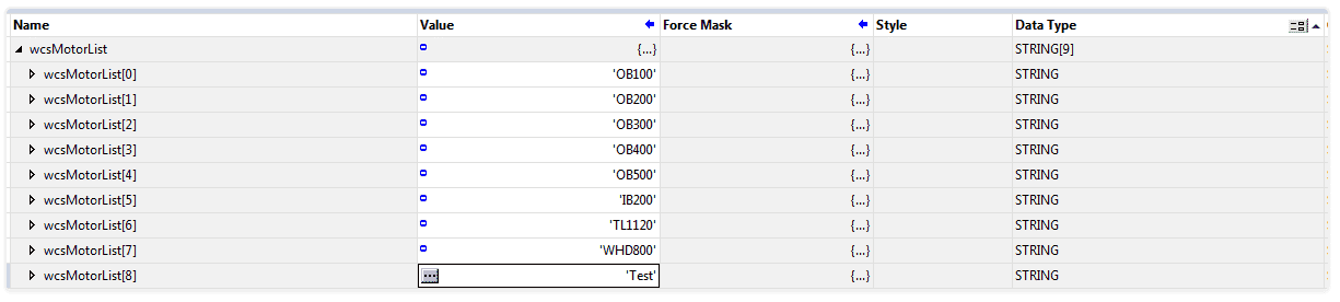
Step 1, will be to create an array of Strings in the PLC. There should be one element in the array for each motor you wish to be controlled manually. E.g. if you have ten motors, the array of Strings will be 10 long, or elements 0-9.
The tag name of the Array must be “wxsMotorList”.
Within the elements of the array, list the Motor Names as you would like shown on the WXS. E.g. P100 or OB600
Step 2, will be to add/create a UDT that provides the available tags for the Manual Control. There will be two UDTs needed for Manual Control. One is a Pushbutton (Active/Enable) UDT and the other is for Fixed and Variable, Uni and Bi-Directional Control.

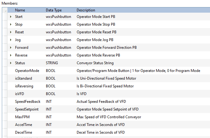
Step 3 would be to create tag names for each of the Motor names as they are listed within the wxsMotorList array. Therefore, using this example, we would create a new tag called “OB100” and assign it data type wxsManualMotor. Thus giving you OB100.Start.Active, OB100.Start.Enable, OB100.Stop.Active and so on and so forth.
A breakdown of the UDT elements:
Pushbutton sub-elements:
-
.ActiveWrite from WXS to PLCThis is set TRUE when the WXS user clicks on the Start button, and is set to FALSE 500ms later.
-
.EnableRead from PLC to WXSThis is used to enable or disable the pushbutton on the WXS. For example, it is common practice to only set enable to TRUE when the PLC is allowing the WXS to have manual control; e.g. when in Operator Mode. Another example would be to have all buttons disabled while in Program Mode, then when switched to operator mode, only the Start is enabled while the motor is off. Once the motor turns one, perhaps the Start is disabled and the Stop becomes enabled.
-
Start.Active (Start.Enable)
- User choice
-
Stop
- User choice
-
Reset
- User choice
-
Jog
- User choice
-
Forward
- User choice
-
Reverse
- User choice
-
Actuate (BOOL)
- User choice (only for Actuator)
-
Status
- This is the String text that displays on each Manual Motor Portlets in the WXS screen. Generally, this text would be, as example, “Ready to Run”, “Running”, “Faulted”, etc.
-
Operator Mode
- This is TRUE when the WXS user requests for the control of the Motor to be placed into Operator Mode and FALSE when they request it to be placed back into Program Mode.
-
isStandard
- The PLC to write 1 to this tag to tell the WXS that this Motor is Uni-Directional Fixed Speed Motor.
-
isReversing
- The PLC to write 1 to this tag to tell the WXS that this Motor is Bi-Directional Fixed Speed Motor.
-
isVFD
-
The PLC to write 1 to this tag to tell the WXS that this Motor is Variable Speed Controlled.
- Note: this is generally used when the PLC has control of the VFD over comms and can control such elements as: Speed, Accel Time, Decel Time
-
-
isActuator
- The PLC to write 1 to this tag to tell the WXS that this is a Solenoid
-
Speed Feedback
- PLC to write the speed, as INT to this tag
-
Speed Setpoint
- PLC to read this tag, as INT, from the WXS and can be used at the discretion of the programmer. Such that, this setpoint can be for only Operator Mode or can be for both, Operator and Program Mode Speeds as the user sees fit.
-
Speed @ 60Hz
- This is the Speed in Feet Per Minute @ 60Hz the conveyor was designed to go. This is used for FPM or Percentage calculations. This number should be the field literal, and not a nameplate.
-
Accel Time
- This is the Accel Time as INT for the VFD
-
Decel Time
- This is the Decel Time as INT for the VFD